Project Objective & Problem Statement
Standard residential solar panels are typically installed in a fixed position, a compromise that significantly limits their energy-capturing potential throughout the day. This project addresses this inefficiency by designing a dynamic, single-axis solar tracking system.
The objective was to develop and simulate a robust control system that enables a solar panel to rotate on its vertical axis, tracking the sun’s position to maximize energy generation.
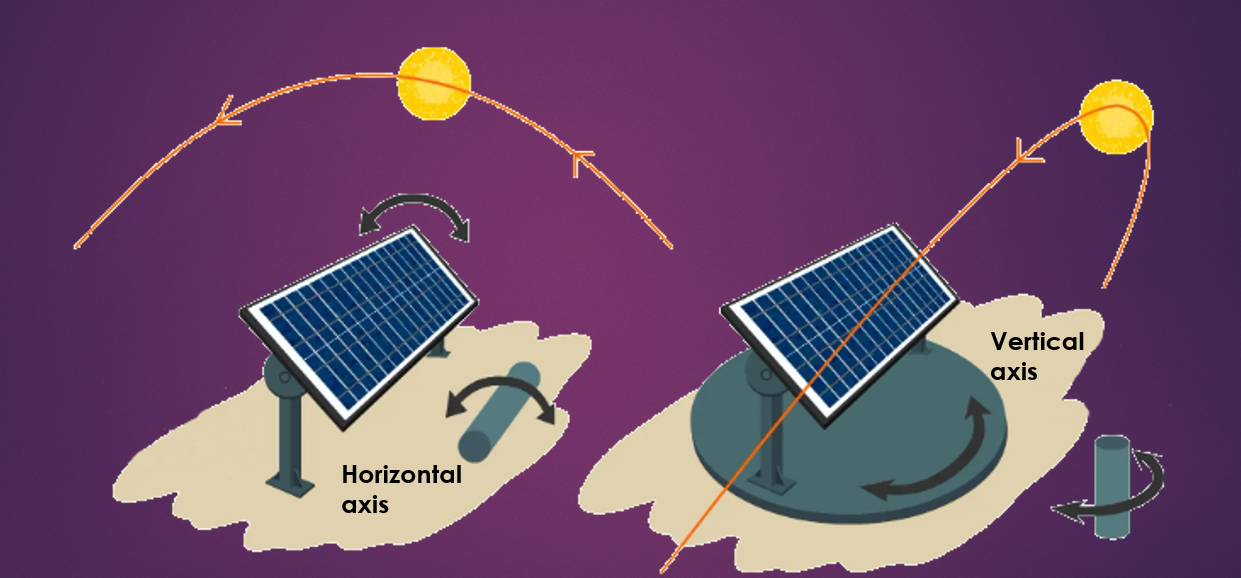
Conceptual illustration of a dynamic solar panel. This project focuses on the vertical axis rotation (right) to track the sun’s daily path.
I. System Modeling & Parameterization
The first step was to create a high-fidelity mathematical model of the electromechanical system. This involved defining the core components and sourcing realistic parameters to ensure the simulation would be representative of a real-world system.
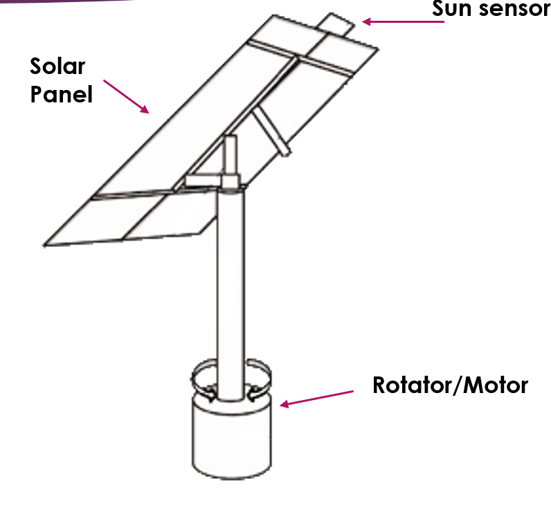
The core components: a sun sensor provides the target angle, and a DC motor rotates the panel assembly to match it.
I modeled the system using standard equations of motion for a DC motor and a rotating inertial load. To ground the simulation in reality, I researched typical specifications for small-to-medium DC motors and solar panel assemblies to estimate key parameters like motor inductance (L), resistance (R), rotational inertia (J), and mechanical damping (Kd).
II. Control System Design & Tuning
With a parameterized model, the next step was to design the control logic.
PI Controller Selection
Given that the sun’s movement is slow, predictable, and continuous, a full PID controller was unnecessary. The derivative (D) term, which primarily acts to counteract rapid changes, would add complexity with little benefit. A Proportional-Integral (PI) controller was the ideal choice, providing the necessary precision to eliminate steady-state error without being overly aggressive.
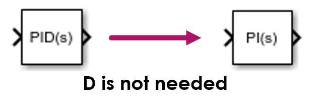
The controller was simplified from PID to PI because the derivative (D) term was not required for a slow, predictably moving target.
Iterative Tuning Process
I performed manual tuning of the PI controller in Simulink to optimize the system’s response. The process was iterative:
- Proportional Gain (Kp) Tuning: I first increased the Kp value to achieve a fast response time, getting the panel to move quickly towards the target position.
- Integral Gain (Ki) Tuning: With a responsive system, I then introduced and gradually increased the Ki value to eliminate the steady-state error, ensuring the panel would perfectly align with the target over time.
- Final Adjustments: I made minor adjustments to both Kp and Ki to find the optimal balance, minimizing overshoot while maintaining a fast settling time.
III. Simulink Implementation & Verification
The entire system was implemented in Simulink using a modular, subsystem-based approach. This allowed for independent verification before full system integration.
Subsystem Verification
I first built the motor and rotator subsystems separately. I applied step inputs to each to verify their open-loop behavior, ensuring the motor produced the expected torque and the rotator responded correctly before connecting them into the final closed-loop configuration.
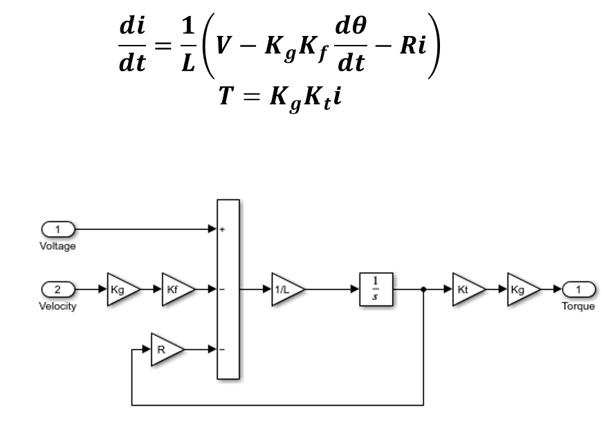
The motor’s equation of motion and its verified Simulink subsystem, which translates voltage into output torque.
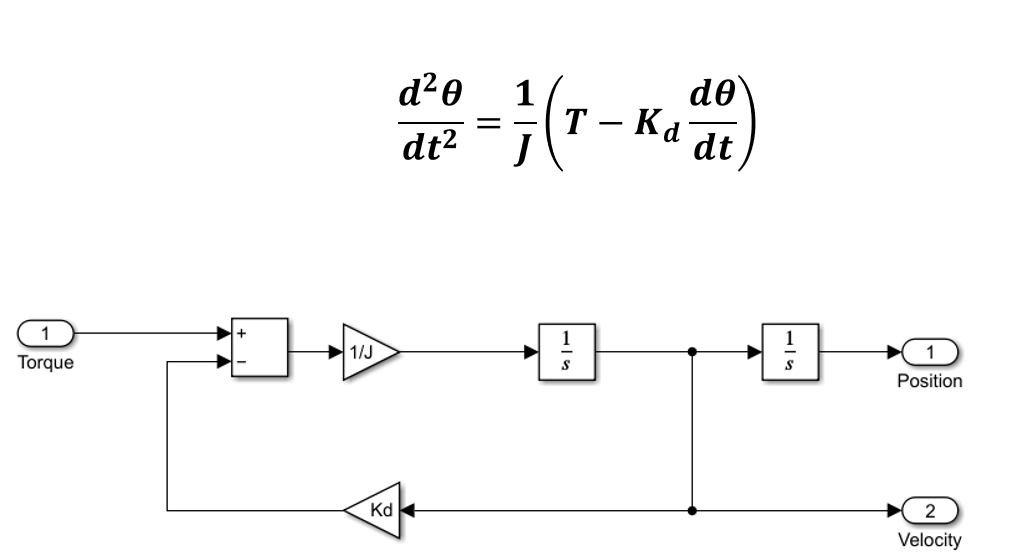
The rotator’s equation of motion and its verified Simulink subsystem, outputting the panel’s position and velocity.
Final System Integration
After verifying the subsystems, I integrated them with the tuned PI controller to form the complete closed-loop system.
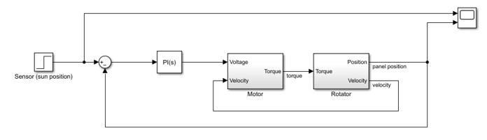
The final integrated system in Simulink, showing the closed-loop signal flow from sensor to controller to plant and back.
IV. Results & Analysis
The simulation results validated the effectiveness of the design and tuning process. The system demonstrated a stable and accurate response to a change in the sun’s target position.
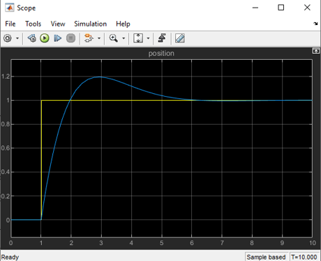
Simulation results: The system’s position (blue) shows a well-tuned response, reaching the target setpoint (yellow) with a fast settling time and minimal overshoot.
The graph shows the system achieving a settling time of approximately 2-3 seconds, which is more than adequate for tracking the sun. The slight overshoot was deemed acceptable as it quickly dampens, and the system stabilizes precisely at the target.
V. Conclusion & Recommendations for Future Work
This project successfully demonstrated, through modeling and simulation, that a PI-controlled system can effectively and efficiently orient a solar panel to track the sun. The methodical approach of parameterization, iterative tuning, and modular verification resulted in a robust and high-performing simulated system.
The primary area for future development is addressing the potential for a net energy deficit on overcast days. I recommend the following enhancement for a hardware prototype:
- Implement Power Monitoring: Add a sensor to measure the panel’s real-time power output.
- Add a “Low-Power” Mode: If the energy generated falls below the threshold required to power the motor, the control system should automatically enter a power-saving state, ceasing tracking until conditions improve. This would ensure the feature is always energy-positive.
Key Skills Demonstrated:
- System Modeling & Parameterization: Translating a physical system into a high-fidelity mathematical model in Simulink.
- Control Systems Design: Selecting and justifying the use of a PI controller for a specific application.
- PI Controller Tuning: Hands-on, iterative tuning to optimize system response for stability and performance.
- Model Verification & Validation: Employing a methodical, subsystem-based approach to test and debug a complex model.
- MATLAB & Simulink: Proficient use of simulation tools for design, analysis, and validation.
- Critical Analysis: Identifying practical limitations (energy deficit) and proposing actionable engineering solutions.